











KoCAD · Pantallas y funciones
How to turn a 2D drawing (DXF/DWG) into a 3D part
Convert the views of a DXF into a solid, or take the outline to a sketch and extrude it.
Este artículo aún no está traducido a su idioma: se muestra la versión en English.
En esta página
What this is for
A lot of work arrives as a customer DXF or DWG. Instead of redrawing, KoCAD uses the drawing views to build the 3D part, or takes the outline to a sketch.
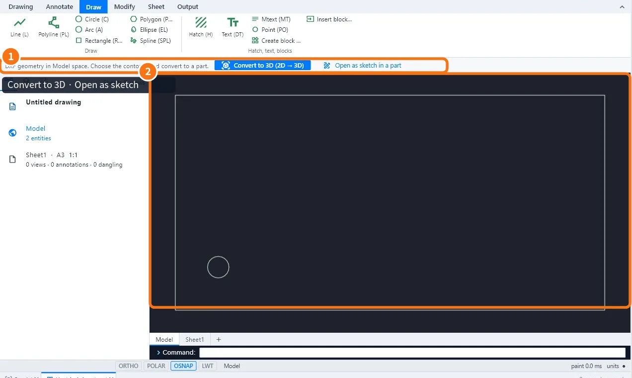
Route 1: Convert to 3D (views → solid)
- File → Open… and choose the DXF or DWG. It opens in the 2D workspace ②.
- In the bar ① click Convert to 3D (2D → 3D).
- Select the outlines of each view (front, top, side) when KoCAD asks, and check the scale and units.
- Review the proposed part. Sizes the drawing does not give become editable assumptions.
- Apply and save as .kcpart.
Route 2: Open as a sketch in a part
- With the DXF open, select the outline of the part.
- Click Open as a sketch in a part.
- A new part opens with the outline in a sketch. Check the dimensions.
- Extrude with the sheet thickness. Done.
Common mistakes
- Outline does not close: the DXF has loose ends; join them in the 2D workspace (Trim, Extend, Join) before converting.
- Part at the wrong scale: the DXF was in inches or at a sheet scale; confirm units and scale in the conversion.
- Views swapped: check whether the drawing is first or third angle and choose the same projection.
Related articles
- Workflow: from a drawing (photo, PDF, DXF, DWG) to a 3D model
- How to draw over a photo or drawing (image reference)
- Drawing 2D from scratch: command line, precision and DXF