











KoCAD · 界面与功能
How to flatten sheet metal and make the laser DXF
See the flat pattern, check blank, cut length and pierces, and save the DXF with cut and bend layers.
此文章暂无您的语言版本,以English显示。
本页目录
What this is for
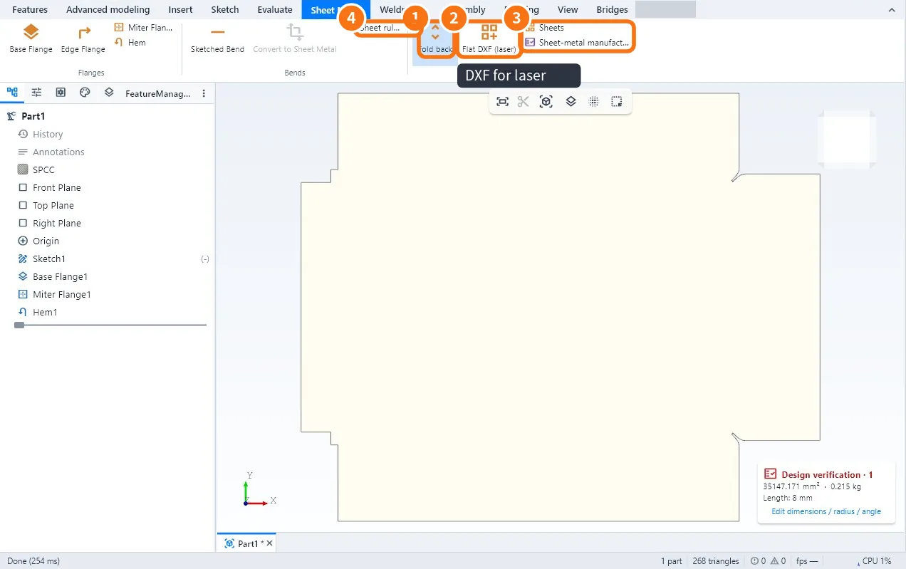
The laser cuts flat sheet. Flatten unfolds the bent part and shows the shape that goes to cutting, with the bend allowance already applied. Flat DXF (laser) saves that outline in a file the cutting machine reads.
Step by step
- Open the sheet-metal part and click Flatten ①. The part lies flat; click again (Fold) to go back.
- Check the Blank size (rectangle around the part), the Cut length, the number of Pierces and the area.
- Click Flat DXF (laser) ②. Choose the name; KoCAD suggests the project's 03 · DXF folder. You can also export an SVG/DXF contour for the shared jig with the Station, using the Sheet / item / quantity wizard (all slots, one, first N, or tap the drawing) while keeping the physical position.
- Take the file to the machine or send it to the cutting supplier.
Laser artwork preview
The preview now shows the image in every copy, including its physical rotation and mirroring. Check all six images before generating the path; recipes and CAM are unchanged. Identical material warnings appear once.
What the DXF looks like
- Item · Value
- Format · DXF R12, text in Shift-JIS (read by Japanese machines and most cutting software)
- Cut layer · AM_0 (green) = outline and holes
- Bend layer · AM_3 (yellow) = bend lines, for marking or checking
- Scale · 1:1 in mm
Sheet nesting ③
- Click Sheets (Flat pattern group).
- Enter the available sheet sizes and the number of parts.
- KoCAD lays out the parts and shows how many sheets to use and the yield.
Common mistakes
- Flat size differs from the real part: the K-factor or deduction is not your press brake's; adjust it in the Base Flange.
- Bend lines get cut: the machine is cutting layer AM_3; set it to cut AM_0 only.
- Flatten is grey: the part is not sheet metal; use Convert to Sheet Metal or build it with Base Flange.
Related articles
- How to create a sheet-metal part: base flange, flanges, mitres, hems and bends
- Workflow: sheet metal → flat pattern → laser DXF → nesting
- How to export DXF and DWG (3 views, flat pattern and 2D drawing)
- How to convert a solid (or a STEP) to sheet metal and check manufacturability