











KoCAD · Screens & features
Print & Cut: prepare 3D parts and laser work
Choose your machine, prepare and inspect a part or drawing, and export files. Optionally connect a station on your own network. An internal KOREOS account is not required.
Open Print & Cut on the ribbon and choose 3D Printer or Laser. Follow the steps on the left and inspect the preview on the right. Start with your own machine and its matching profile; another person's profile does not establish compatibility.
If your machine is missing, open the profile menu and choose New manual profile. Enter its usable area and travel limits. For 3D printing, also check nozzle and filament diameters, material and temperatures. Follow the manufacturer's specifications and instructions. Origins, calibration, speeds and start/end commands belong to that specific machine; do not copy another machine's calibration.
For 3D, use the document's part or import an STL. Adjust orientation, position and scale, then check dimensions and bed limits. Show the part zooms in; Whole bed shows the available area. Fitting inside the displayed bed does not replace checks of your printer's setup, material and operating conditions.
Choose a layer height, walls, infill and temperatures suited to your material and nozzle, then slice. Automatic mode can use PrusaSlicer installed on this PC or a connected station's slicer. The external PrusaSlicer always receives vase mode off, even if the station's base profile enables it; walls, top layers and infill set in KoCAD are preserved. KoCAD's basic slicer is for preview and estimation and does not generate supports; its result alone is not a validated manufacturing process.
Inspect layers, toolpath simulation, estimated time and filament consumption. Actual duration depends on the machine and the conditions specified by its manufacturer. You can open a text G-code file to inspect its preview and export G-code or SVG without pairing a station. Check the file format, limits and destination profile before using it.
For laser work, use a sketch, a part view or flat pattern, import SVG/DXF, or select an engraving image. Each colour of the drawing becomes a layer with three steps: Contour, Engrave (fill) and Cut. Every step has its own on/off toggle, power, speed, pass count and air setting. The fill step additionally offers line interval, back-and-forth, overscan and direction. KoCAD sends the drawing and its steps to the station, and the station itself generates the G-code. Press "Compute on the station" to see the estimated time of each step and the real toolpath before sending.
The "New drawing" button in the laser panel creates a rectangle or a circle filled for engraving, with an outline around it placed on its own layer—for example, a cork coaster. Cork is now in the materials list with the station's recipes: engrave at 30 % power, 12 000 mm/min, 0.1 mm line interval, overscan 1.1 mm. A DXF file with several layers also becomes one laser layer per DXF layer.
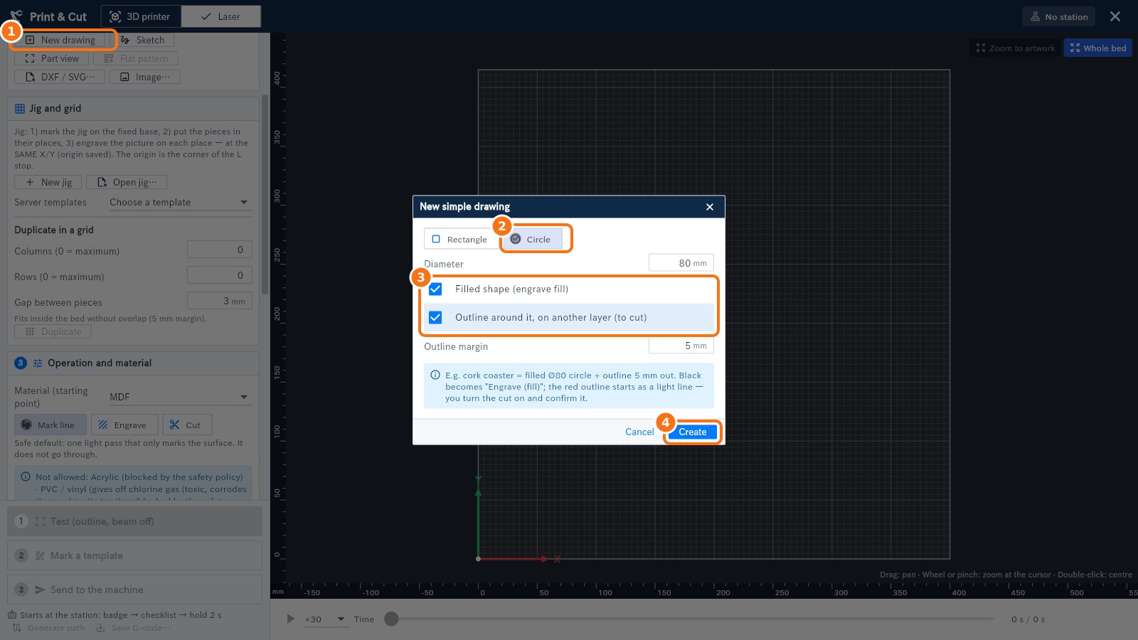
New drawing (KoCAD 0.43.6): ① click New drawing, ② pick Circle (or Rectangle), ③ filled shape to engrave + an outline around it on its own layer, to cut, ④ Create.
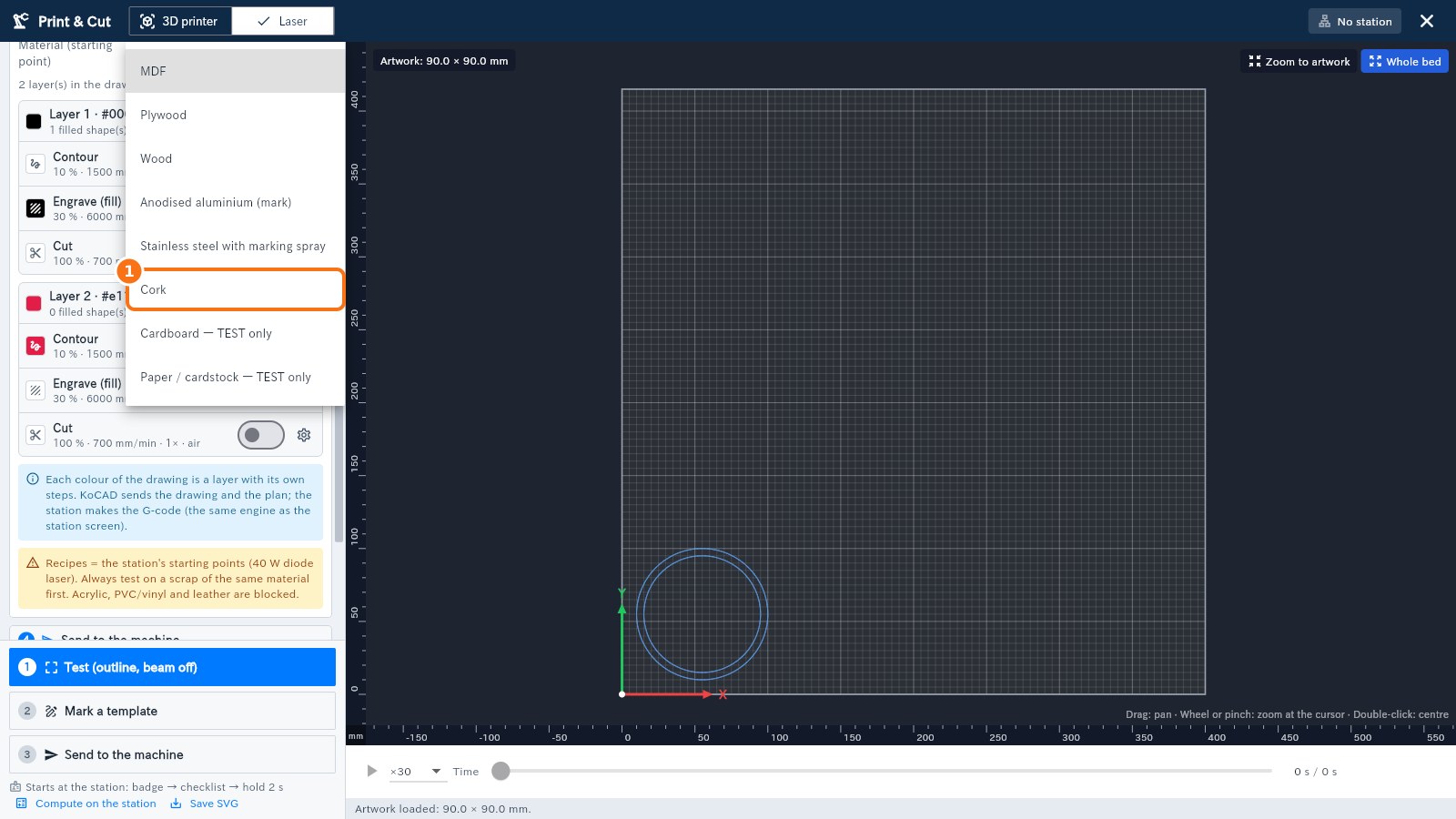
① Cork in the material list — it applies the station recipe (engrave at 30 %, 12,000 mm/min, 0.1 mm line interval, 1.1 mm overscan).
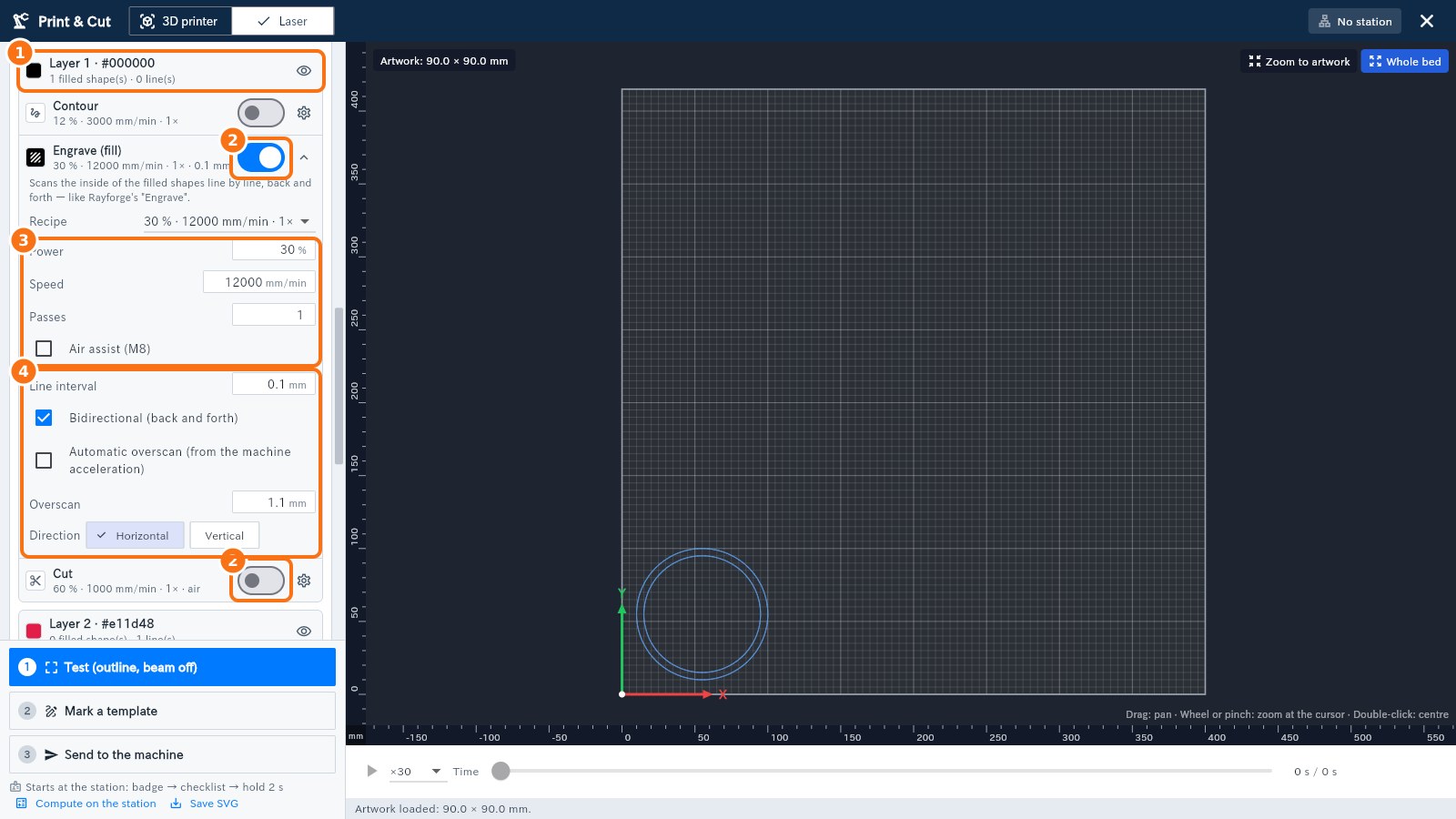
① Each colour of the drawing becomes a layer; ② every step (Contour, Engrave (fill), Cut) has its own on/off; ③ power, speed, passes and air; ④ for the fill: line interval, back and forth, overscan and direction.
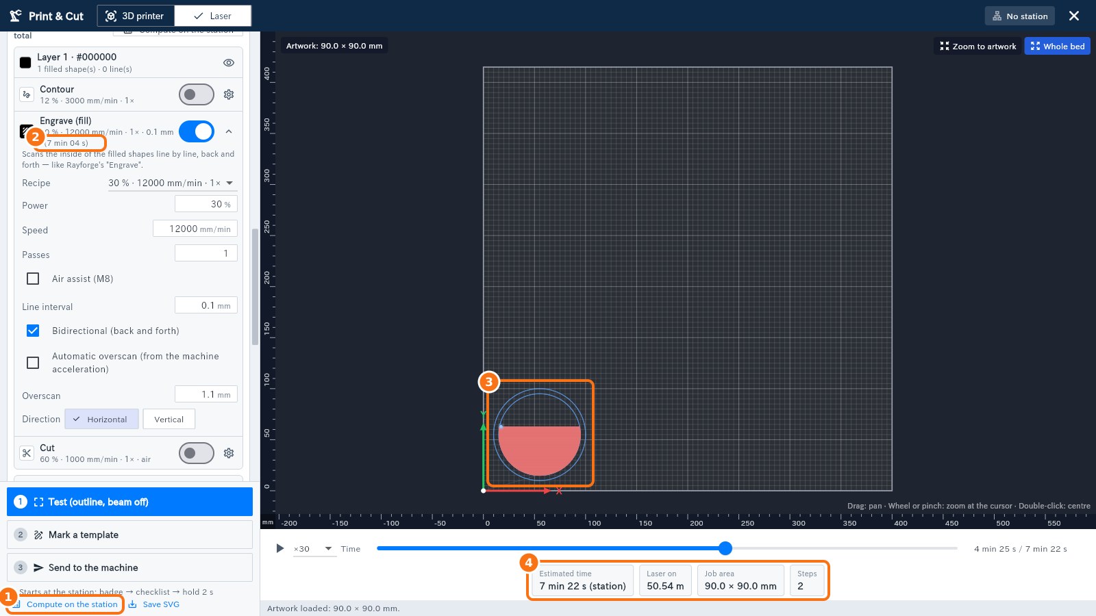
① Compute on the station: ② the time of each step, ③ the real laser path in the preview and ④ the total time from the station, before you send.
A Cut step never starts turned on. When you enable it, KoCAD asks for confirmation before proceeding; changing the cut parameters or the material triggers the confirmation again. On the machine, all cut steps run last, after every engraving pass has finished. The station refuses to execute a cut that has not been confirmed. Power, speed, pass count and material compatibility depend on your machine and its specific profile; confirm them with the manufacturer and operator.
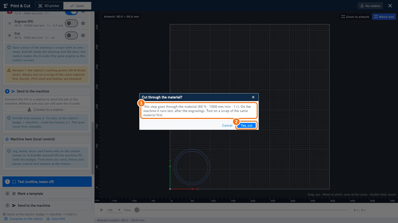
Turning Cut on asks first: ① the cut goes through the material and runs last, after the engravings; ② the step is only on after Yes, cut.
In Jig / Layout, define the sheet, outlines, spacing and occupied slots. Check every copy against the physical part positions, including when using only selected slots. Generate and inspect the toolpath. Without connecting a station, you can export artwork or jig outlines as SVG and toolpaths as G-code, as appropriate for the operation.
To send over the network, open Stations and machines and search your own network or enter your station's address manually. Pair using the code shown by the station and follow that installation's secure TLS connection setup. Commercial accounts do not need an internal KOREOS account; KOREOS integrations apply only to authorized internal accounts. Use addresses, pairings and profiles belonging to your account and installation.
Preparing a new job is separate from inspecting work already running. In Machine here, select the local machine and the large central preview shows the active job. Toggle between 3D Part and Toolpath; completed work appears in blue and the current position is marked. The preview uses that job's data; when no original model is available, a simplified representation is shown and identified. Estimated positions are labelled and do not replace the original model or a measurement. When status is unavailable, wait for the connection and a current reading; unavailable does not mean idle.
Exporting, pairing, viewing a preview or preparing the queue does not authorize a physical start. If the station's start feature is enabled, follow its permissions and checks: badge, checklist and a 2-second hold. Laser starts are local to the machine PC. Check material, fixing, thickness, recipe and your installation's safety conditions before starting; use that machine's own profile and calibration.