











KoCAD · Screens & features
How to create a sheet-metal part: base flange, flanges, mitres, hems and bends
From outline to bent bracket, with the right thickness, bend radius and K-factor.
On this page
What this is for
The Sheet Metal tab models bent parts the way the shop makes them: a flat sheet of constant thickness, bent along lines. KoCAD keeps thickness, radius and K-factor, so it can flatten the part and produce an accurate laser DXF.
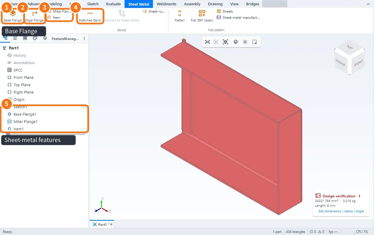
Step by step
- Draw a sketch with a closed outline (lines and arcs). Inner circles and outlines become holes.
- Click Base Flange ①. In Sheet metal parameters enter the Thickness t, the Bend radius (inner) and the K-factor (or the 90° bend deduction). Confirm.
- Click Edge Flange ② and click the straight edges of the sheet (several = one flange each). Enter Flange length, Angle, Up / Down and the Flange position (material inside, material outside or bend outside). Use start/end offsets to get a bend relief.
- To go round corners, use Miter Flange ③: click consecutive edges of the base and enter the corner gap.
- To fold the edge 180°, use Hem (closed or open, with a gap).
- To bend the sheet along any line, draw the line in a sketch on the face and use Sketched Bend ④.
- Check the features in the tree ⑤ and save.
Tips
- Each flange can have its own radius; the others use the sheet radius.
- Flange length can be measured to the outer virtual sharp, the inner virtual sharp or from the bend tangent — use the same rule as your drawing.
- KoCAD's default K-factor is 0.44; replace it with the value your press brake confirmed (Sheet rules keeps it per material and thickness).
Common mistakes
- "Create the base flange first": the other sheet-metal commands only work after it.
- The flange does not appear: the clicked edge is not straight or is an inner edge; click the outer border.
- Flanges clash at the corner: use Miter Flange or offset the ends.
Related articles
- Sheet Metal tab: flanges, bends, flat pattern and laser DXF
- How to flatten sheet metal and make the laser DXF
- How to convert a solid (or a STEP) to sheet metal and check manufacturability