










KoCAD · Bắt đầu
Simple mode: draw, give thickness, drill and get the drawing and DXF — no CAD experience needed
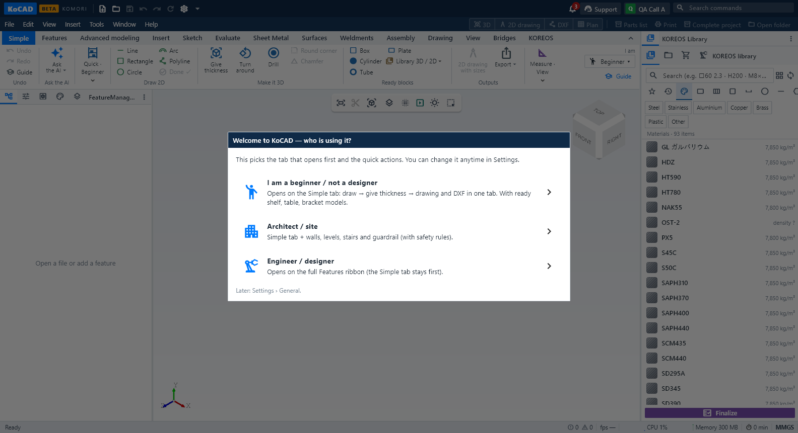
For people who are not designers and never used a CAD or SolidWorks. The Simple tab is the first one of the ribbon and opens by itself the first time (when you choose "I am a beginner" or "Architect/site"). The full ribbon stays on the other tabs.
Bài viết này chưa được dịch sang ngôn ngữ của bạn: đang hiển thị bản English.
Trong trang này
Who it is for For people who are not designers and never used a CAD or SolidWorks. The Simple tab is the first one of the ribbon and opens by itself the first time (when you choose "I am a beginner" or "Architect/site"). The full ribbon stays on the other tabs.
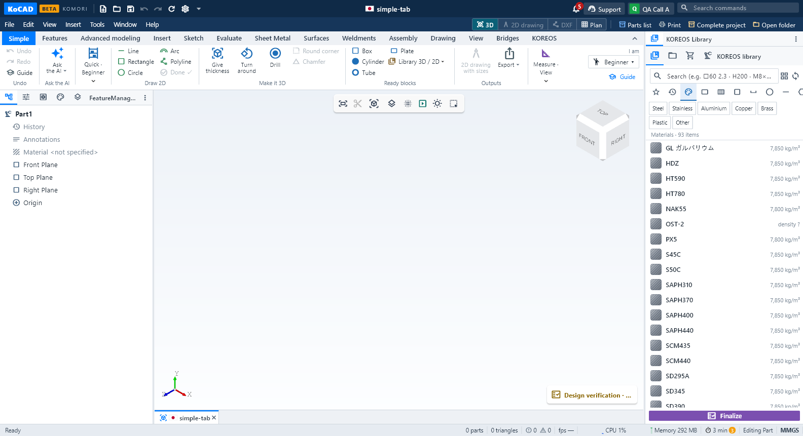
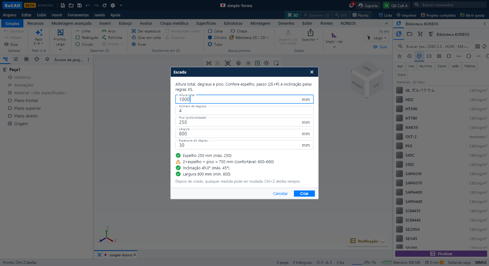
The order of the tab (left to right) 1. Undo / Redo — always in view. A mistake? Undo (Ctrl+Z). 2. Ask the AI — Bob. Click an example and the text is written for you; it is sent only when you click Send. 3. Quick · (your profile) — ready models with a size form. Beginner: shelf, table, L bracket, sheet box, machine base. Architect/site: room walls with a door, levels (slabs), stairs and guardrail (safety rules checked as you type). Engineer: bent sheet (U), welded frame, standard holes and Check. 4. Draw 2D — Line, Rectangle, Circle, Arc, Polyline, right on the plane you are looking at. After the first click, type the size: 150 (line), 200x100 (rectangle), 50 (diameter) and Enter. "Done ✓" finishes. 5. Make it 3D — Give thickness (one number), Turn around, Drill (centre / 4 corners / row), Round corner, Chamfer. 6. Ready blocks — Box, Cylinder, Tube, Plate (click, or drag onto the 3D view) and Library 3D / 2D. 7. Outputs — 2D drawing with sizes (automatic, A3, front/top/side + 3D) then PDF, DXF and print; Export DXF / PDF / STEP; Bill of materials; Print. 8. Measure — Measure (distance, angle, area), Weight (asks the material when missing) and Dimension. 9. View — 3D ⇄ 2D, Cut to see inside, Explode (assemblies).
Right corner: I am ▾ (Beginner / Architect-site / Engineer) changes only the quick actions; Guide opens the walk-through.
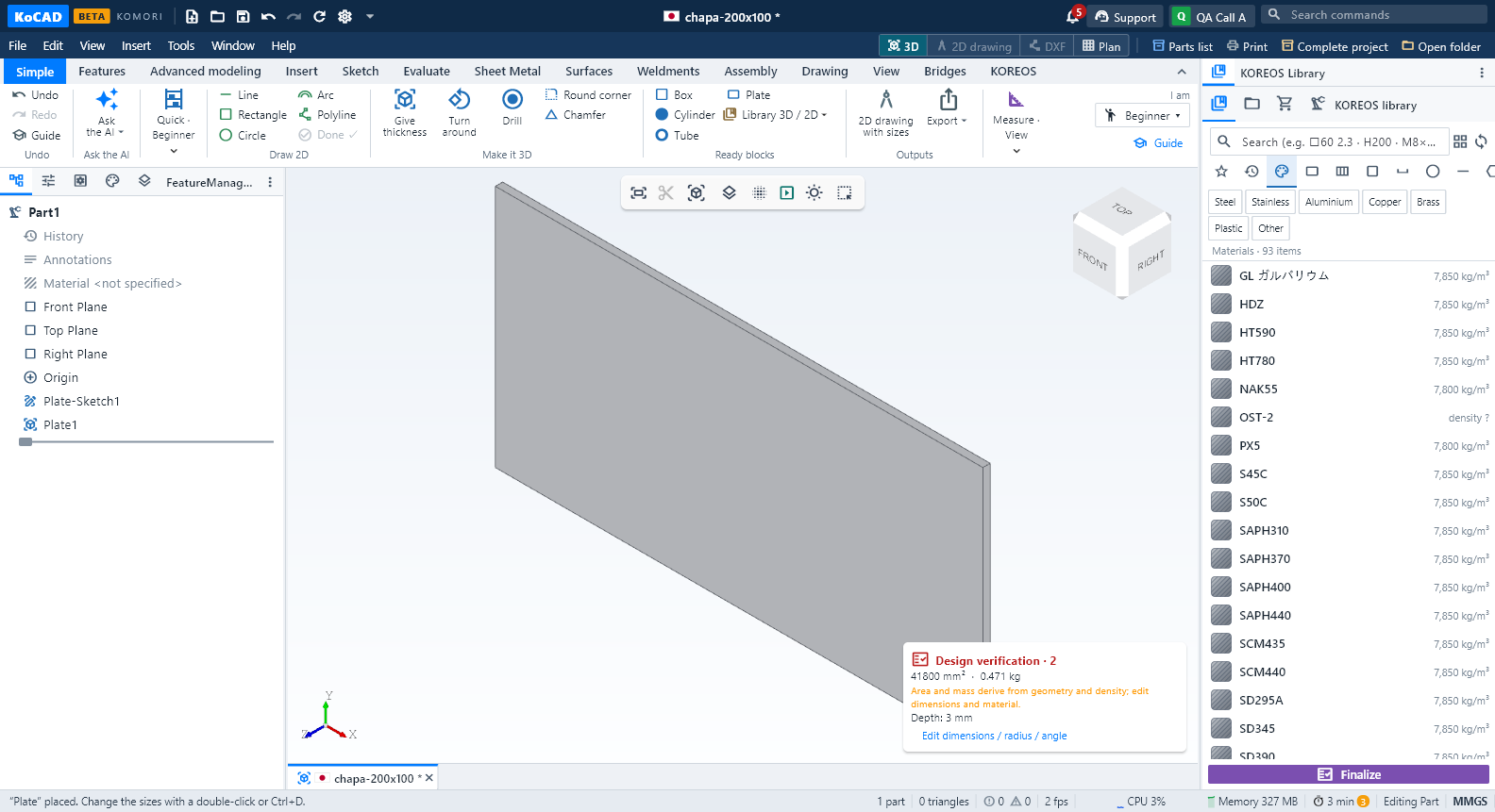
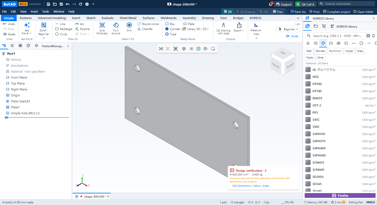
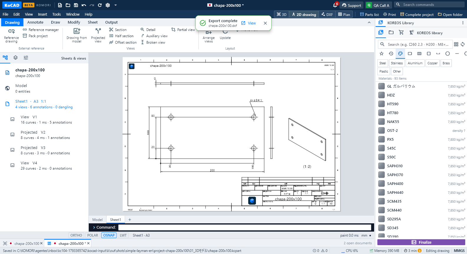
The 3-minute test: plate 200 × 100 × 3 with 4 holes, dimensioned drawing and DXF 1. Simple → Plate → Width 200, Height 100, Thickness 3 → Create. 2. Drill → "4 corners" → Hole diameter 9, Edge to hole centre 20 → Drill. 3. 2D drawing with sizes → (the part is saved first; choose its name) → the A3 drawing appears with its dimensions. 4. In "Drawing ready": DXF → choose the folder → done (PDF and Print in the same box).
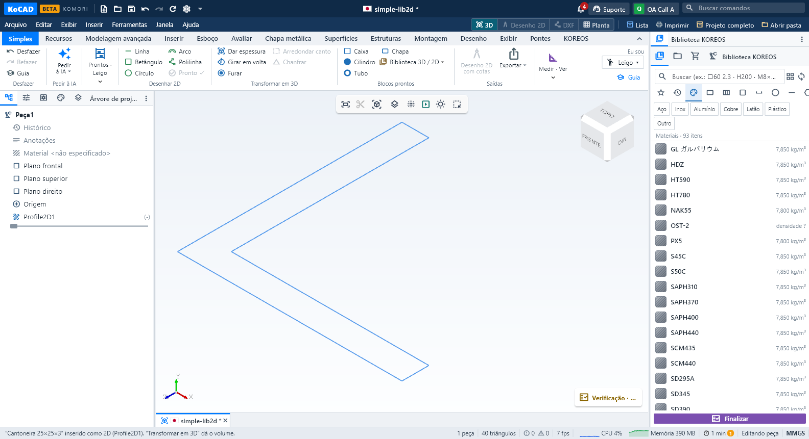
Library: 3D or 2D In the library, right-click a part: Insert as 3D (part/solid) or Insert as 2D (outline/view) — the section of an angle, tube or beam, the outline of a plate or the head of a bolt, dimensioned. On a placed part, right-click: Turn into 2D (dimensioned outline; other parts: the drawing views). On a closed 2D outline: Turn into 3D (with the item's length/thickness). The big Library 3D / 2D button has the same menu.
CAD words (glossary in the tooltips) Hovering the buttons of the full ribbon shows "In plain words": extrude = give a closed drawing thickness; fillet = round a corner; sketch = a 2D drawing on a plane; revolve = turn half a profile around an axis…
It is all ordinary Everything the Simple tab makes is an ordinary feature of the tree (sketch + extrude, hole, structural member, sheet metal). People who know more keep editing in the full mode: double-click or Ctrl+D changes the sizes; Ctrl+Z undoes one action at a time.
Settings Settings › General: Who uses it, Tab that opens first (Automatic / Simple / Features) and Show the first-steps guide again.